





The Home Energy Model thermal mass calculation considers both how much heat a building element can store and where that heat-storing material sits relative to insulation.
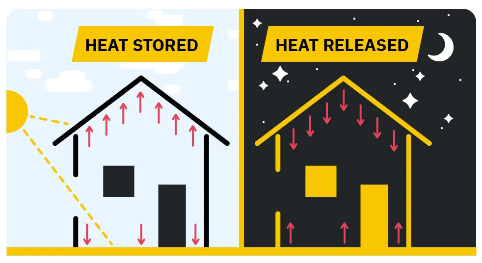
A home’s walls, floors and roof can store heat and release it later. This ability is known as thermal mass, and it forms part of how the Home Energy Model (HEM) calculates a building’s energy performance.
For energy assessors and anyone learning about HEM, understanding how the model handles thermal mass helps explain how it represents different constructions. Let’s take a closer look.
How does the Home Energy Model measure thermal mass?
HEM uses a value called areal heat capacity for each building element. This describes how much heat each square metre of the element can store for each degree of temperature change. The value covers the element’s entire thickness. This differs from the kappa value used in SAP, which considers only the part of the construction active in storing heat at the internal surface.
Areal Heat Capacity: The amount of heat a building element can store per square metre for each degree of temperature change. It is measured in J/(m²K) – joules per square metre per kelvin. In HEM, it includes the entire thickness of the building element.
The Home Energy Model thermal mass methodology follows BS EN ISO 52016-1:2017. This standard provides default heat capacity values for construction classes ranging from very light to very heavy. Examples include light board or plastic at the very light end, and solid brick or heavyweight concrete more than 12 cm thick at the very heavy end.
Why does the position of thermal mass matter?
HEM considers where the main mass sits within a construction, alongside its heat capacity. Each building element is assigned one of five mass distribution classes, describing the position of its mass relative to its thermal resistance:
- Internal side (I): the main mass is near the inside surface, as in a construction with external insulation.
- External side (E): the main mass is near the outside surface, as in a construction with internal insulation.
- Internal and external sides (IE): the mass is split between two main components, with insulation between them.
- Equally distributed (D): the mass is spread through the construction. Uninsulated brickwork is one example.
- Centre of the construction (M): the main mass sits between internal and external insulation.
For example, a solid wall with internal insulation has a different mass arrangement from one with external insulation. These classes allow HEM to represent that difference in its calculations.
How is thermal mass included in HEM’s calculations?
Each opaque building element, such as a wall, roof or floor, is represented by five connected calculation points called nodes.
HEM allocates the element’s heat capacity across these nodes according to its mass distribution class. The nodes become part of the heat flow network for the zone being modelled, and the heat balance equations for all nodes in that zone are solved together.
This is how the Home Energy Model thermal mass calculation connects heat storage in building materials with heat movement through the building.
It should be noted that transparent building elements are treated differently, HEM ignores their thermal mass.
What about air and furniture?
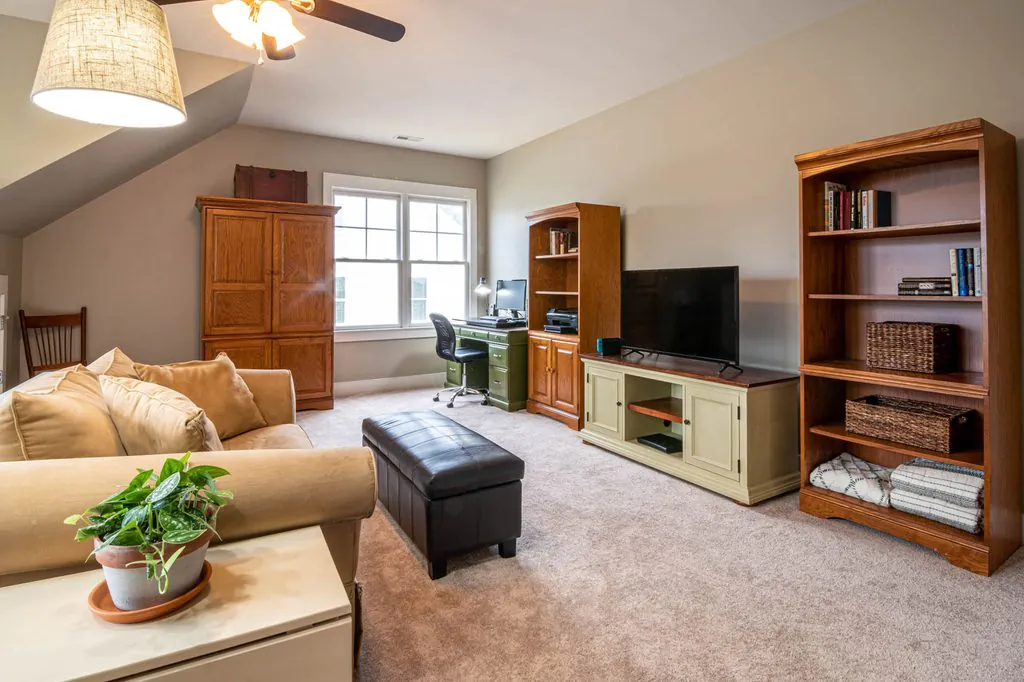
Building materials are only part of the picture. HEM also includes a fixed allowance for the thermal mass of air and furniture. This allowance is 10,000 J/K per square metre of zone floor area, following the suggested default in BS EN ISO 52016-1:2017.
It represents air and furniture together, rather than requiring a separate heat capacity calculation for every item of furniture.
How does HEM treat underfloor heating?
Heat emitters and underfloor heating systems have their thermal mass represented separately within the emitter model. Their thermal mass remains linked to the zone’s temperature calculation, including when the heating is switched off.
HEM also avoids counting the same thermal mass twice. Where part of a floor forms an underfloor heating emitter, that part’s thermal mass is excluded from the floor building element’s thermal mass. It is accounted for through the emitter model instead.
What is the Heat Capacity Parameter?
Alongside its detailed calculations, HEM produces a single figure for the dwelling called the Heat Capacity Parameter (HCP). This is calculated by adding the heat capacities of the building elements across all zones and dividing the result by the total floor area.
The HCP provides a figure for reporting and comparison. It is not used in the main heat balance calculation, which uses the individual building elements and their nodes.
This distinction helps when interpreting Home Energy Model thermal mass results: the whole-home reporting figure serves a different purpose from the detailed calculation.
What should energy assessors keep in mind?
There are a few factors that energy assessors, or anyone working with HEM should keep in mind. The five mass distribution classes are approximations of real constructions. Some building arrangements fit them more closely than others. For instance, the technical document gives the example of a solid brick wall insulated internally with insulated plasterboard. If this is assigned to class E, the plasterboard’s thermal mass is not represented at the internal node. For some constructions, choosing the appropriate class is also less than straightforward.
Understanding how HEM treats thermal mass therefore means looking at both the materials’ heat capacity and their position relative to insulation. For energy assessors, recognising these details—and the limitations of the available classes—helps make sense of how a home is represented in the model.
You can read the full explanation in the government’s ‘Calculating thermal mass within the Home Energy Model‘ technical documentation.